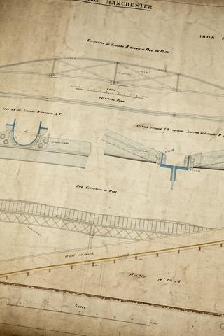
Drawings of Robert Stephenson's steam engine Rocket by John Dobson Wardale
History.
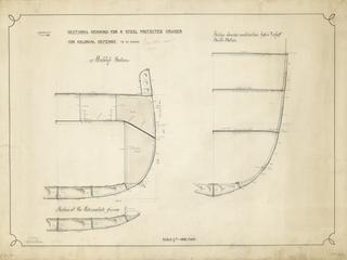
Drawing entitled 'Sectional Drawing for a Steel Protected Cruiser for Colonial Defence to be named'
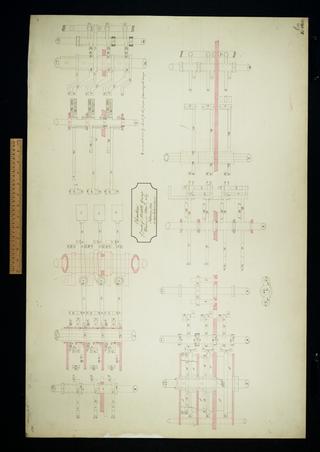
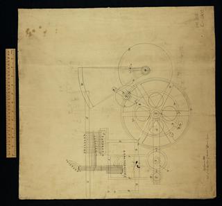
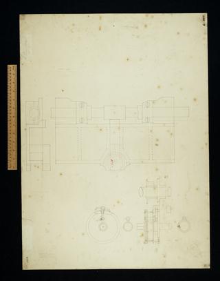
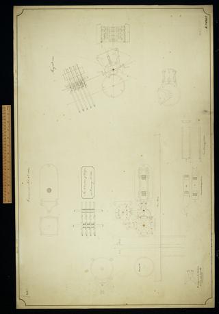
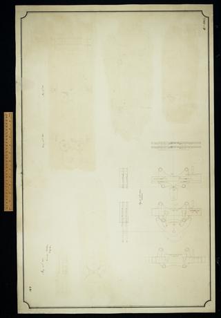
Elevation of parts of middle group drawn in plan on No. 127.
History.
History.
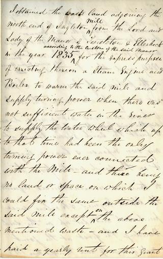
A note relating to the steam engines at the Ingleton Mill

Notation of units
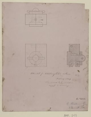
Sketch of mould for adding column collars.
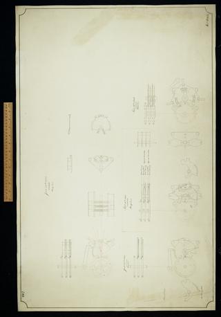
Part of the end view of the Difference Engine

Notation of units

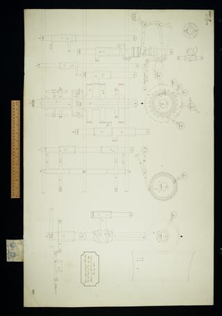
Locking motions for carriage column.

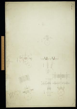
Plan of the left half to middle group for General Plan 28.
Sign apparatus for Plan 28a. Plan, elevation.
Plan of consecutive mill counting apparatus for General Plan 28. Plan, note.

Plan and elevation for the calculating part of the Difference Engine. Figure 1. Superseded. Consecutive carriage.

Sketch of an apparatus for advancing stereotype frames of the Difference Engine by cranks and backing them by weights. Superseded. Plan, elevation.

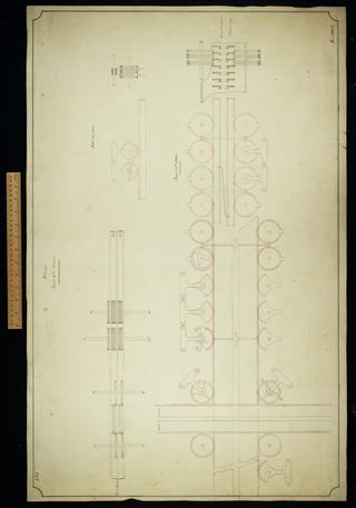
Axes D1 E1 for the left hand group of Plan 28. Plan, elevation.

Plan titled, 'Various arrangements proposed, examined and rejected between the rejection of Plan 27 and the adoption of Plan 28. Figures 1, 2, 3, 4, 9. Various', and a folded sheet of notes

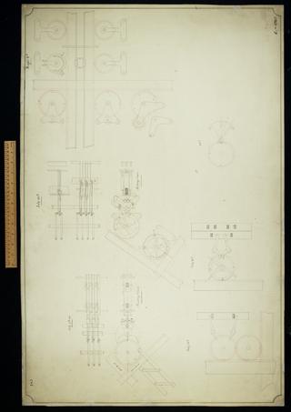
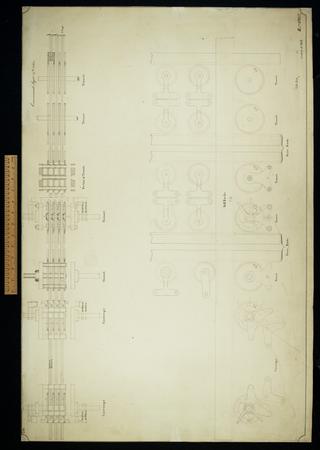
First sketch of all the parts in plan of the right half to middle group of General Plan 28. Plan, elevation.

Sundry axes and wheels for Plan 28.

Speculations on the driving and directive for the Difference Engine. Superseded. Arrangements.

Improved framing for centre group of Plan 28. Arrangement, plan.

Difference Engine wheels for driving the cranks which move the matrix frames. Superseded. Plan, elevation.

Untitled. Plan of locking plates for locking axis circularly and vertically.

Speculations on the driving and directive of the Difference Engine. Superseded. Arrangement.

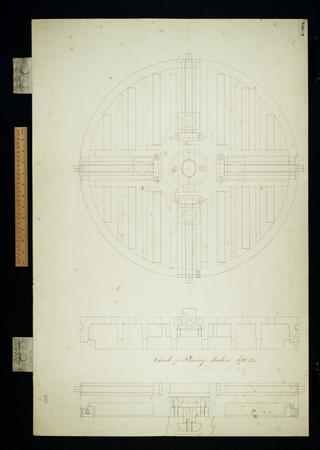
Plan and elevation of a platform for giving circular motion to axes applied as an experiment to the Difference Engine No. 2. Drawing 163.

Parts of the slide for the Planing machine. Plan, elevation.

Parts of the slide for Planing machine. Plan, elevation.

Anticipating whole and half zero digit counting carriage. Plan, elevation and details.

Elevation of parts of the card counting apparatus for operation and variable cards.

Figures 1 and 2. Sketches of a tens chain for carriage for whole and half zero. Plan, elevation.

Motions of the printing apparatus
Chuck for Planing machine. Plan, elevation.

Motions of the stereotype frames

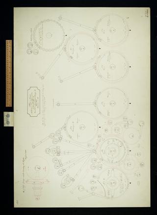
Circular motions of the calculating axes
Part of the Planing machine.

Motions of the stereotype frames

Parts of slide for the Planing machine. Plan, elevation

Sketch of an apparatus for lifting the axes of the Analytical Engine. Plan, elevation.
Untitled, showing details of parts, including figure wheel to receive addition.
Untitled. Shows details of mill and store racks, and breaking and making chains.
Untitled pencil layout, includes mill racks.
Untitled sketches of various machine parts such as carriage, store rack, warning arm, wedges bars and tens warning slides. Plans and elevations.
Half zero details including warning plate.
Untitled. Probably a plan and elevation of mill rack connections.
Probably a plan and elevation showing store and mill racks.
Details of circular pattern half zero. Incomplete.
